The LHCb note describing the FEB may be found at FEBnote (preliminary)
FEB/CAT Version Compatibility
Date |
CAT |
lbXCAL |
|---|---|---|
31/01/08 |
v3r0 |
v1.6 |
Latest version of the lbXCAL package
FEB installed in the FSM
The FEB you want to use has been installed by an expert. You simply want to use it. If not go to the next section Installing a FEB (most probably a Crate) in the FSMGetting access to a FEB already installed in the FSM
You should first have a DNS server running and connect a SpecsServer to it.Using the FSM Device Editor

Open the PVSS project and start the Device Editor. You should be in the Navigator mode (see example on the left).
Open the right tab called FSM. You will see the name of your project after the sys icon (in the example, HCDAQC1).
Clicking on the + symbol, you should open the hierarchy of devices included into the FSM structure of your project. The example contains a HCAL_DAQ control units that includes four others.
The FEB may appear as a single board, but usually it should be a board located into a crate. This is the case in our example as the FEB we may edit belong to the crate 22 of the hadronic calorimeter. The crates belong to the HCAL_DAQ structure of the FSM tree. If you open it, you will see the HCAL crates driven by the project, HCAL 22 and HCAL 23, the two crates connected to the pc hcdaqhvc01w.
hcdaqhvc01w is the pc that drives the two HCAL crates of the side C of LHCb.
From a desktop shortcut
That's the easy way. You should have a shortcut linked to the Calorimeter FSM hierarchy. You may navigate down to your crate and the FEB you wish to look at.Standard Configuration (Recipe)
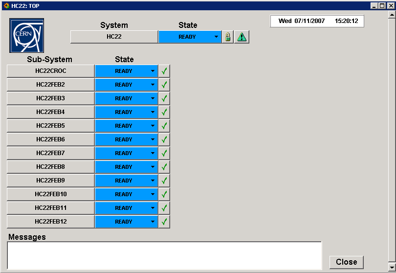
Right click on the crate you want to have a look at (here HC22 for crate HCAL 22) from the FSM tree, and select the view option. This should open a window similar to the one below except from the fact that the FEBs and the CROC are probably in NOT_READY mode. You may either press the NOT_READY button of the full crate or specifically of the FEB choosen and select Configure. The default configuration (called PHYSICS) should be proposed and you should accept this default.This last action will load the PHYSICS recipe and apply it to the FEB(s).
After a delay, the NOT_READY button (yellow) should turn into a blue READY one. You may now select START. This has no real effect on the FEB as it is ready to accept new L0 when it gets to the READY mode. The RUNNING state is used in order to reset counters or start some monitoring.
Configuring a FEB manually

The standard settings are mostly those of the screen capture above. The L0 Latency and BXIdReset settings may change in the future.
The FEB panel is divided in several subparts described below.
Derandomizers
LED
Resets
Sequencer Configuration
Front-End Configuration
Derandomizers
Derandomizers
Not implemented yet. The idea is that if something is wrong a red button will appear to indicate that a power cycle occured on a board, the temperature is in a strange range or the boards are not properly synchronized and the header detection performed by the CROC showed that the boards do not download the events synchronously.Slot power
If a short circuit occured on a board a delatcher circuit temporarily switched off part of the corresponding board. This was detected by the CROC which kept track of the problem even if the board is powered back. Its configuration is now probably wrong and it is not synchronized with respect to the other FEB. A red light should appear above the board which had the problem.The update button permits to refresh the corresponding information.
The Control line permits to manual stop powering a board. This control will act on the delatcher circuit and switch off the power on most of the components of the board. Pressing the control button above a board will switch between the ON and OFF states. Then you should apply the new configuration. This has to be used with cautions: the board will certainly not recover from such a power cycle without a full reconfiguration !
The ALL ON an ALL OFF button allow to easily power on/off the full crate. Pressing CLEAR will give you a chance not to do anything !
Crate ID and Temperature
The crate ID should not be changed as this value is sent by the CROC in the DAQ data words. This is looked at by the event builder which will probably be not happy to see another crate talking to the TELL1 connected to it. The value should be the crate number.You certainly imagine that if you got to that point in the tutorial, you should understand what the temperature is... Have a look at the value. The temperature is not yet calibrated : 1920 is typically what you may expect.
Resets
There exist several resets for the CROC. You may choose to entirely reset the crate or the CROC only Notice that the first include the second. In both case, the SPECS mezzanine of the CROC will switch from the CROC clock to its own internal clock. Working in such (asynchronous) conditions is hazardeous and you should redirect the CROC clock to the SPECS mezzanine after such an operation. This operation is done automatically but if not you may force it with the Clk Redir button.The meaning of the other reset is understandable from the name of the button.
Slot Configuration
The slot configuration is divided into two main parts. The graphical view shows what the CROC knows about the actual configuration of the crate. The update button at the top of the panel permits to refresh the graphical view.The series of buttons called Sel. FEB allows to mask a FEB which is not present or that should be masked (if it is not functioning satisfactorily). The Clear/Fill button unselect/select all the board. Its is required to acknowledge the operation with apply.